The most well-known method for constructing a regular pentagon causes it to be inscribed in a given circle with a known center. It’s easy to find, on-line or in textbooks, and I will not be reproducing that construction here.
Because the diagonals and sides of a regular pentagon are in the golden ratio, it is also not difficult to construct a golden rectangle, and then use it to construct a regular pentagon. Given the ease of finding instructions for constructing a golden rectangle elsewhere, though, I’m not posting that construction here, either. This one begins with two distinct points, A and B, and the segment which connects them. The goal here is to start with only that, and then construct a regular pentagon, with sides of length AB, using only the methods permitted for Euclidean constructions.
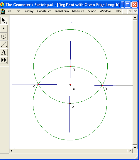
After segment AB has been drawn, the next step is to continue it, in both directions, to form line AB. Next, construct two circles, each with radius AB: one centered on A, and the other centered on B. These circles must intersect at two points, labeled C and D, as shown above. The next step is to construct line CD, and label, as point E, the intersection of lines AB and CD. This is the well-known procedure for constructing the perpendicular bisector of a segment, so E is the midpoint of segment AB, and the four angles with vertices at E are each right angles.
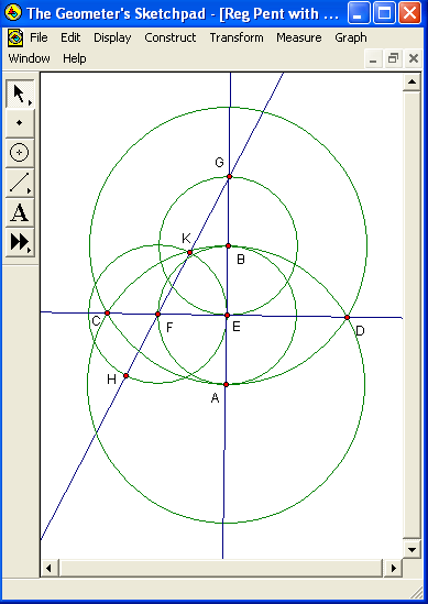
Next, construct a circle, centered on E, with radius AE. Label, as point F, the intersection of this circle with segment CE. After than, construct a circle, centered on B, with radius BE. This circle intersects line AB at two points, one of which is already labeled E. Label, as point G, the other such intersection. At this time, because they are all radii of equal-sized circles, the following lengths are equal: AE, BE, BG, and EF. Segment EG, however, is twice as long as any of these shorter and equal-length segments, since it is a straight segment formed by combining non-overlapping segments BE and BG. Since the same can be said for segment AB as well — its length equals AE + BE, or 2AE by substitution and addition — it follows that AB = EG. The next step is to construct line FG, which necessarily includes segment FG. Since segment FG is the hypotenuse of right triangle EFG, which has one leg (segment EG) which is twice as long as the other leg (segment EF), it follows, from the Pythagorean Theorem, that the distance FG is equal to the distance EF times the square root of five. Next, construct a circle which is centered at F, and has segment EF for a radius. Label the intersections of line FG, and this circle, as points H and K, as shown above, with K being the closer of the two to point G. Now there are two new segments, FH and FK, which, because they are radii of the same circle as segment EF, are each equal in length to segment EF, as well as to segments AE, BE, and GB, each of which were already shown to be equal in length to EF, and half as long as either of the equal-length segments EG and AB.
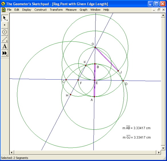
The next step is to construct a circle, centered at G, with radius EG. After that, consider the collinear and adjacent segments FH and FG, which, together, compose segment GH. FH is one of the several segments known to be half as long as AB, and FG’s length is already known to be equal to this shorter length (that of segments EF, FH, AE, etc.) times the square root of five. By the segment addition postulate, then, segment GH’s length is equal to the length of one of the shorter segments AE, EF, etc., times the sum of one and the square root of five. This length, GH, will be used as the diagonal-length of the regular pentagon, because GH’s length, and the edge length originally provided (AB), are in the golden ratio, since segment AB is twice as long as segment EF, and GH is equal to EF times the sum of one and the square root of five. GH is the radius of the next circle to construct, and that circle should be centered at H. This circle, the largest yet constructed, intersects the radius-EG circle centered at G at two points. One of these intersection-points, on the same side of line AB as right triangle EFG, need not be labeled, but the other one, on the other side of line AB, should be labeled as point J, as shown above. Segments GJ and EG, then, have equal lengths, for they are radii of the same circle — and the distance EG has already been shown to be equal to the distance AB, so GJ = AB as well. The segments GJ and AB are highlighted in pink in the diagram above, with their lengths shown, in order to provide additional evidence that their lengths are equal.

In the diagram above, segment GJ is shown in bold, because it is a side of the pentagon being constructed. Segment HJ is then constructed, and is also shown in bold, for it is a diagonal of that same pentagon, having the correct length by virtue of being a radius of the same circle as segment GH, which was already shown to have the correct length for a diagonal of the pentagon. The next step is to locate point L, which will be a vertex of the pentagon. To do that, construct a circle of radius HK, centered on H. Because segment HK is formed by the non-overlapping, adjacent, and collinear segments FH and FK, each of which has the same length as AE or AB, it follows that HK, the radius of the last circle constructed, is equal in length to both AB and GJ, with this distance being the side-length of the pentagon being constructed.
Next, construct a circle which has radius GH (the diagonal-length of the pentagon), and is centered at G. This circle, and the already-constructed circle with radius HK which is centered at H, intersect at two points. Label one of these points of intersection (the one on the same side of line AB as point J) as point L, as shown above, and then construct pentagon-sides HL and JL, also shown in bold in the figure above. (Also shown: measured lengths of all segments rendered in bold thus far, as well as AB.) Of these last two circle-intersection points, one has now been labeled as point L. The next step is to label the other such intersection as point M, as shown in the diagram below.

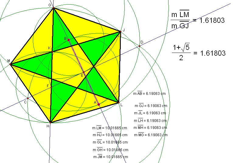
Once point M is located, the remaining sides and diagonals of regular pentagon GJLHM can be constructed, as shown above, in bold, simply by connecting each remaining unconnected pair of pentagon-vertices with a segment. The lengths of all bold segments, plus the original segment AB, are also shown above. As you can see, all five sides have length equal to the length of segment AB, while all five diagonals have a length greater than that of AB, but one which is constant throughout the set of diagonals.

In the diagram above, no new objects have been constructed using the Euclidean tools, but the pentagon has been given color, and a check of the diagonal-length to side-length ratio has been performed. As you can see, in the uppermost calculation, the decimal approximation for this distance-ratio is given as 1.61803. The same result is obtained, in the second calculation shown, when the sum of one, and the square root of five, is divided by two — and, since this is the definition of the golden ratio, obtaining the same result, for both of these calculations, provides supporting evidence for the validity of this construction.

To perform one more test of this construction — one only possible with a virtual compass and straightedge, such as Geometer’s Sketchpad, the one I used here — points A and/or B can be moved around. I chose to move them both, and I also increased the distance between them. As you can see, this increased all the side and diagonal lengths, as well as the length of the original segment, AB. However, segment AB still has the same length as all five pentagon sides. Also, all five diagonals, while they do have a longer length than any side, still have lengths equal to each other. Also, the diagonal-length to side-length ratio remains constant, at the value of the golden ratio, even though the actual distances all changed when A and B were moved. The construction, and its explanation, are now complete.