Unknown's avatar

About RobertLovesPi

I go by RobertLovesPi on-line, and am interested in many things, a large portion of which are geometrical. Welcome to my own little slice of the Internet. The viewpoints and opinions expressed on this website are my own. They should not be confused with those of my employer, nor any other organization, nor institution, of any kind.

Euclidean Construction of a Four-Part Compound Eye

one

North American Geographical Oddity

You’re standing on the mainland of North America — not on an island. From where you are, you can travel due East, and you’ll come to the Pacific Ocean. If you travel due West, however, you will come to the Atlantic Ocean. What’s more, this is true for a relatively large percentage of locations in the country where you are located — a greater percentage than would be the case for any other country on the North American continent, if there even are others.

In what country are you standing?

(Scroll down for the answer.)

.

.

.

.

.

.

.

.

.

.

.

panama

You’re in Panama! Now, before anyone protests that Panama is in Central America, not North America, let me point out that Central America is part of the North American continent, just as Europe and India are part of the Eurasian continent. (Yes, I looked them up.)

A Great Dodecahedron with Peepholes

Compound of Dodeca and dual

If anyone is inside this polyhedron, they can see you!

Software credit:  see www.software3d.com/Stella.php.

A Polyhedron with 602 Faces and Icosidodecahedral Symmetry

602 faced Convex hull

I used Stella 4d:  Polyhedron Navigator to make this. You can try this program as a free trial download at www.software3d.com/Stella.php.

Icosahedron with Tessellated Faces

Icosa

The images on the faces of this icosahedron appeared on this blog three posts ago, and were created with Geometer’s Sketchpad and MS-Paint. To project this image onto this polyhedron, and then generate this rotating .gif, I used a third program, Stella 4d. You may try this last program yourself, as a free trial download, at www.software3d.com/Stella.php.

Three Superimposed Hexagonal Tessellations Can Make a Triangular Tessellation

trihex

A Survey of Right Angles in Convex Heptagons

heptagons

In how many ways can different numbers of right angles appear in convex heptagons?

Heptagons do not have to have right angles at all, of course. If a heptagon has exactly one right angle, only one arrangement is possible:  a right angle, and six oblique angles (“oblique” means non-right, so it includes both acute and obtuse angles).

With two right angles, there are three possibilities. In the first one shown, the right angles are consecutive. In the second, one oblique angle appears between the right angles. In the third, two oblique angles appear between the right angles. Increasing two oblique angles to three is simply a repeat of the third three-right angle heptagon, so this set stops with exactly three members.

With three right angles, I have found four possibilities:  (1) all three right angles appear consecutively; (2) two right angles are consecutive, and one of them has one oblique angle between it and the third right angle; (3) two right angles are consecutive, and each of them has two oblique angles between it and the third right angle; and (4) None of the three right angles is consecutive. In this heptagon, the number of oblique angles which appear between the three different right-angle pairs are one, one, and two.

I have found no others, and, after searching to exhaustion, I do not think any other arrangement of right and oblique angles in a convex heptagon is possible. However, this is a conjecture, not a proof, and may, in fact, be incorrect. If you can provide proof that this listing of possibilities is complete, or a counterexample to show that it is not, please leave a comment with details.


Alternating Triangular Tessellation with Arcs

alternating triangular tesselation with arcs

Circumsinusoidal Regions, Part Two

[Note:  If you haven’t yet read part one, it is recommended to read it first, before reading this part.  Part one is the most recent post here, before this one.]

In part one, a special circumsinusoidal region was described, bounded by parts of semicircles, and a sine or cosine wave.  As previously described, this requires that the wave’s amplitude be exactly one-fourth the wavelength. Of course, most sinusoidal waves do not have amplitudes and wavelengths that fall nicely into a 1:4 ratio. What happens, then, with the majority of waves — the ones with with other amplitude:wavelength ratios? Can they still be used for forming circumsinusoidal regions? The answer is yes — but the cost required is that semicircles may no longer by used in their construction.

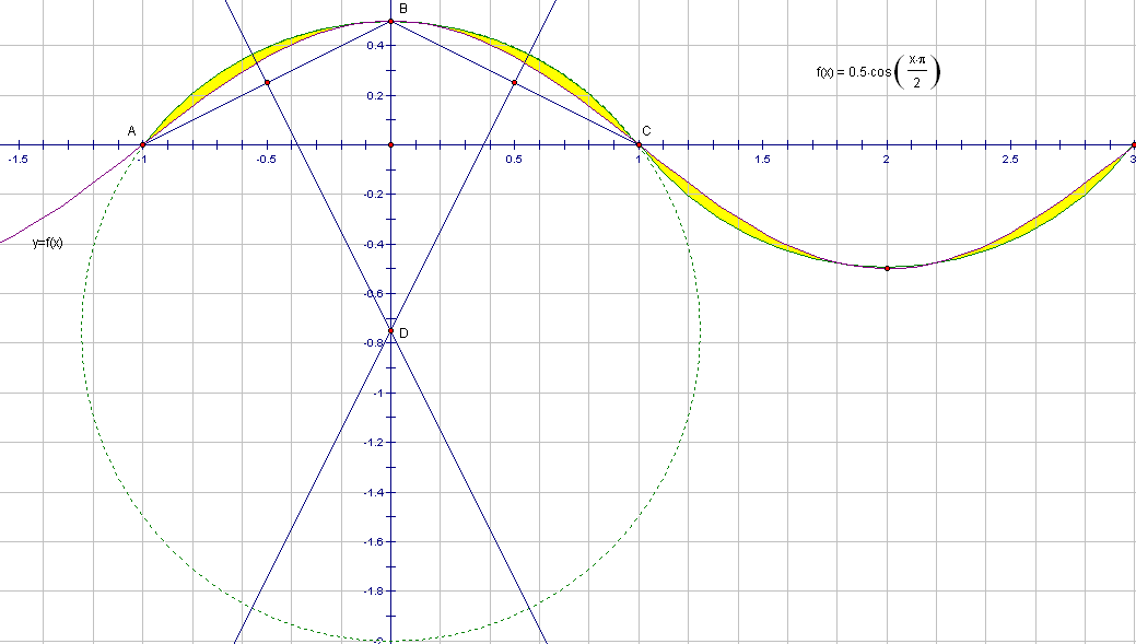
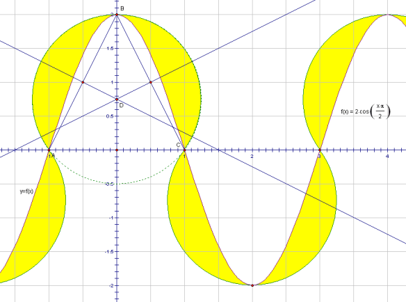
A semicircle can be thought of as a 180 degree arc, if the diameter, often considered part of its perimeter, is ignored. When the sine or cosine wave’s amplitude:wavelength ratio is not equal to 1:4, the only necessary adjustments for the circular arcs needed to define particular circumsinusoidal regions are identical changes in the angular size of each arc used, plus translations of the centers of the circles which contain each of these circular arcs. These translations move those circle-centers away from the line representing the wave’s rest position, in a direction perpendicular to that line. There are two cases to consider:  shorter-amplitude waves (those with an amplitude:wavelength ratio smaller than 1:4), and taller-amplitude waves (where the same ratio is greater than 1:4). The first picture below shows the shorter-amplitude case.

circumsinusoidal region short version

For every half-wavelength which starts at the rest position, an arc through three points is needed for the outer bound of the circumsinusoidal regions, which are shown in yellow. Those three points are two consecutive points (such as A and C above) where the sinusoidal wave crosses the rest position, plus the point at the top of the wave crest (such as B), or the point at the bottom of the trough, exactly half-way along the sinusoidal curve, in-between the two consecutive rest-position points under examination. In this example using points A, B, and C, above, the circle containing those points was constructed by drawing segments AB and BC, and then constructing the perpendicular bisectors of those two segments. Thone perpendicular disectors intersect at some point D, which is the center of a circle containing A, B, and C. The part of this circle which is not used for the arc through A, B, and C is shown as a dashed arc, while the arc used is shown as a solid curve. For other half-waves, to the left or right of this circle and arc, the construction would proceed in the same fashion, but is not shown, for the sake of clarity.

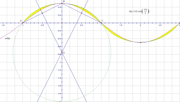
The taller-wavelength case also can be constructed, using the same procedure, as shown below.

circumsinusoidal region tall version

These regions, of course, have area. To determine the exact area of any circumsinusoidal region requires integral calculus, and this area is equal to the difference in the areas under two different types of curve. Without calculus, the best that can be found for these areas are mere approximations, not exact answers. I am leaving this find-the-area problem for mathematicians who have a better understanding of calculus than I possess.

Circumsinusoidal Regions, Part One

circumsinusoidal region

The inner boundary of the yellow regions above is a sine curve (technically, a cosine curve, but that’s the same thing, just with a phase shift). The outer boundaries are semicircles. In order for this to work, to form these yellow regions, the semicircle centers (centers of the circles they are each half of) must be directly below peaks, and above troughs, of the sine (or cosine) curve, and vertically positioned at what would be called the rest position in physics. (I’m resorting to use of some physics terminology here, simply because I don’t know the corresponding mathematical terms).

In addition, each semicircle involved must have a radius equal to one-fourth the wavelength of the sine or cosine wave. The two sets of curves cross each other at the rest position, and are tangent to each other at each peak and trough, producing four of these yellow regions per wavelength.

In this case, semicircles could used because I adjusted the wavelength, making it exactly four times the amplitude of the wave. My goal was to compare the two curves, simply to see how well one simulates the other (answer:  not very well at all).  Then, however, I became more interested in the discrepancy between the two, represented by the yellow regions which are outside the true wave, and inside the semicircles which contain that wave. Until and unless I find that such regions already have a different name, I am naming these two-dimensional curved shapes “circumsinusoidal regions.” There are four of them per wavelength of the wave, and two per semicircle. Each circumsinusoidal region has two vertices, but the two paths connecting them are distinct curves. No part of either path contains any length which is a straight segment.

It would be possible to generate interesting solids by rotating circumsinusoidal regions around vertical or horizontal lines, such as the x- or y-axes, or around diagonal lines. Many such solids would be variations of a torus, including the central hole of a torus, but with circumsinusoidal cross-sections replacing a torus’s circular cross-sections. Unfortunately, I do not have the software I would need to generate pictures of such solid figures.

If the wavelength used for a given sinusoidal wave is not exactly four times the wave’s amplitude, semicircles won’t work to enclose the wave with the same points of tangency, but it is still possible to generate circumsinusoidal regions — using something, in their place, other than semicircles. This will be described in part two, which will be the next post on this blog.