Two Different Versions of an Expanded Snub Dodecahedron, Both of Which Feature Regular Decagons

The snub dodecahedron, one of the Archimedean solids, can be expanded in multiple ways, two of which are shown below. In each of these expanded versions, regular decagons replace each of the twelve regular pentagons of a snub dodecahedron.

exp sn dodeca 2

Exp Sn Dodaca

Like the snub dodecahedron itself, both of these polyhedra are chiral, and any chiral polyhedron can be used to create a compound of itself and its own mirror-image, Below, you’ll find these enantiomorphic-pair compounds, each made from one of the two polyhedra above, together with its own reflection.

exp sn dodeca 2 compound of enantiomophic pair

exp sn dodaca Compound of enantiomorphic pair exp snub dodeca

All four of these images were created using Stella 4d: Polyhedron Navigator, software available (including a free trial download) at this website.

Silver Conversion Chart: Troy, Metric, and U.S. Coin Information

silver

I’m most likely to need the information in the top third of this chart, myself, but I continued it all the way through 100 kg, for the benefit of those with much more money to invest in silver than I have.

How much does silver cost, per troy ounce? Right now, it’s in the $15 neighborhood, but that changes all the time. This is the website I use to keep an eye on the “spot” price of silver, but there are many other such sources, as well.

On Pertrigonometric Functions

Pertrigonometric functions are modifications of the three primary trigonometric functions. Unlike the familiar sine, cosine, and tangent functions, the “pertrig” functions include triangle perimeter in their right-triangle-based definitions, which are given in the bulleted list below. The longer form of “pertrigonometric functions” is “perimeter-based trigonometric functions,” and the shorter, informal version is “pertrig functions.”

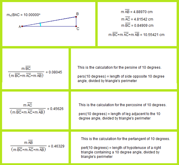
  • The persine of an acute angle (abbreviated “pers”) equals the length of the side opposite that angle, in a right triangle, divided by the triangle’s perimeter.
  • The percosine of an acute angle (abbreviated “perc”) equals the length of the leg adjacent to that angle, in a right triangle, divided by the triangle’s perimeter.
  • The pertangent of an acute angle (abbreviated “pert”) equals the length of the hypotenuse of a right triangle containing this acute angle, divided by the triangle’s perimeter.

After defining these terms, I used Geometer’s Sketchpad to construct a right triangle containing a 10º angle, and then used the “measure” and “calculate” functions to find the values of pers(10º), perc(10º), and pert(10º). Since these are ratios, they would have the same values shown for larger or smaller right triangles which contain 10º angles.

pertrig functions

An observation: the pertangents of complementary angles are equal. Why? Because complementary angles appear in all right triangles, as pairs of acute angles in the same triangle. For each such complementary angle pair, therefore, the same triangle is used to define pertangent. The hypotenuse/perimeter ratio (which is pertangent) would, it follows, remain unchanged — because both its numerator and denominator remain unchanged.  This relationship does not hold for the tangent function; instead, the tangents of complementary acute angles are reciprocals of each other.

Of course, I wanted to know more than just the pers, perc, and pert values for 10º, but I had no desire to repeat the same calculations, many more times, to form a table. Instead, I simply graphed the functions, again using Geometer’s Sketchpad. The units on the x-axis are degrees, not radians.

pertrig functions B

In the graph above, the dark blue curve is the persine function, with the sine function in light blue, for comparison. Similarly, percosine is shown in red, with cosine shown in pink. Finally, pertangent is shown with a heavy, dark green curve, while tangent is shown as a thinner, light green curve.

Entering the equations for these curves was a little tricky, due to the fact that I wanted this graph to venture beyond 0 and 90 degrees, in both directions, on the x-axis. When that is done, the unit circle must be used (in place of right-triangle based definitions), simply because no right triangles contain angles outside this range. The radius of the unit circle is 1, by definition, and that is the hypotenuse of the right triangle which exists in the zero-to-ninety degree part of the domain of the graph above. As a consequence of setting the length of the hypotenuse of each right triangle at 1, the side opposite the angle in question (used for persine) becomes, simply, the sine of that angle, while the adjacent leg’s length is the angle’s cosine. It then follows that the perimeter (the denominator of the pers, perc, and pert ratios) is equal to sin(x) + cos(x) + 1.

Calculations are shown on the graph above, and you can click on the graph to enlarge it, to make them more readable. In these calculations, one more adjustment had to be made, and that was to the perimeter portion of each pertrigonometric ratio. Using sin(x) + cos(x) + 1 works fine for perimeter, for the zero-to-ninety degree portion of the domain, but, outside that, negative numbers intrude, for values of sin(x) and/or cos(x). It is my contention that triangle perimeter only makes sense as a sum of absolute values of a triangle’s three side lengths. To obtain absolute values for both sin(x) and cos(x) in the perimeter-part of each calculation, then, I simply squared each of these two functions, and then took the square roots of those squares. The result of this can be seen on the graph, in the curve for the pertangent function, which resembles a child’s drawing of waves in the ocean. On the y-axis, it never reaches as low as 0.4, and its maximum value is clearly exactly 0.5 — at the sharp “wave peaks.” At the (smooth) troughs, the actual minimum is equal to the square root of two, minus one, or ~0.414, although I have not yet figured out exactly why that is the case — I simply noticed it on the graph — but, to investigate it further, I know where to look: the 45-45-90 triangle, since these minima are hit when x = (45 ± 90n) degrees, where n is any integer. The pertangent function has the shortest period of all the functions shown above, at a mere 90º. For tangent, by contrast, the period is 180º. All four of the other functions shown have periods of a full 360º.

It is striking that the pertangent and tangent curves bear little resemblance to each other, while marked resemblances do exist between the persine and sine curves, as well as between the percosine and cosine curves. In informal terms, the persine curve is a shorter and spikier (but still recognizable) version of the sine curve (vertically, with the amplitude exactly one-half as great for the shorter persine curve, relative to the sine curve), but, horizontally, the two curves are synchronized. The same relationship holds for the percosine and cosine curves. Also, it is well-known that the cosine curve is simply the sine curve, phase-shifted one-quarter cycle (or 90º, or π/2 radians) to the left. This phase-shift relationship between the cosine and sine curves holds, precisely, for the percosine and persine curves.

There is a simple reason why persine, percosine, and pertangent all peak at exactly y = ½. All three functions generalize, for acute angles, to this ratio — (some side of a right triangle)/(perimeter of that same triangle) — and no side of any triangle can ever exceed, nor even reach, half that same triangle’s perimeter. In all three cases, the maximum y-value is only reached, even in the zero-to-ninety degree portion of the domain, for “degenerate cases” — angles of 0º or 90º, which are, of course, not acute angles at all. Interpreted as triangles, these are cases where either a triangle becomes so short that it collapses to a single segment, or the opposite degenerate situation: two parallel lines, connected by a single segment. If you try to make either (or both) of the acute angles in a right triangle into an additional right angle, after all, that’s what you get.

To my knowledge, no one has described these pertrigonometric functions before, by this or any other name, although I could be wrong. (If I am wrong on this point, please let me know in a comment.) Regardless of whether this is their first appearance, or not, I did not invent them. The reason for this is simple: nothing in mathematics is ever “invented” — only discovered — for mathematics existed long before human beings existed, let alone started writing things down. How do I know this? Simple: there was a universe here before there were people, and all evidence indicates that it operated under the same laws of physics we observe today — and all evidence to date also indicates that those laws are mathematical in nature. Therefore, with the “pertrig” functions, I either discovered them, or, if they have been found before, then I independently rediscovered them.

Finally, I’ll address that question so often asked, about numerous things, in mathematics classes: what are these pertrigonometric functions used for? As far as I know, the answer in this case, so far, is absolutely nothing, other than delighting me by their very existence. It is possible that this may change, for someone might find a way to make a profitable application of these functions — and I won’t get any money if they do, either, for I am not copyrighting any of this. Nothing in mathematics is subject to ownership.

Honestly, though, I hope no one ever finds any practical, “real-world” use, at all, for pers, perc, or pert. Right now, they are pure mathematical ideas, unsullied by tawdry, real-world applications, and, well, I like that. I am far from the only person who ever had such an attitude about a mathematical idea, either — such views are actually fairly common in the mathematical community. Most of those who try to discover previously-unseen things in mathematics do so solely, or primarily, for one reason: the joy of discovery, in its purest form.

Slowly Rotating Hyperdodecahedron

This is the hyperdodecahedron, or 120-cell, one of the six four-dimensional analogs of the Platonic solids. It’s been shown on this blog before, but this image has one major change: a much slower rotational speed. It is my hope that this will help people, including myself, with the difficult task of understanding four-dimensional objects.

5-Hi, 120-cell, Hecatonicosachoron

This image was created using Stella 4d, a program you can try, as a free trial download, at this website.

Trinary Rhombicosidodecahedra

Faceted Augmented Rhombicosidodeca

This image of three rhombicosidodecahedra “orbiting” a common center was made with Stella 4d, a program you may try for free at this website.

Tidally Locked Binary Icosidodecahedra

binary icosidodecahedra

I’ve been trying to figure out for over a year how to make images like the one above, without having holes in the two polyhedra, facing each other. At last, that puzzle of polyhedral manipulation using Stella 4d (software available at this website) has been solved: use augmentation followed by faceting, rather than augmentation followed by simply hiding faces.

Two Similar Polyhedra with Icosidodecahedral Symmetry

octagons and kites

Stellated Chjhonvex hull

Both of these were made using Stella 4d, software you can try at this website.

Three Different Depictions of the Compound of Five Cubes

The most common depiction of the compound of five cubes uses solid cubes, each of a different color:

Cubes 5

This isn’t the only way to display this compound, though. If the faces of the cubes are hidden, then the interior structure of the compound can be seen. An edges-only depiction, still keeping a separate color for each cube, looks like this:

Cubes 5 edges

If these thin edges are then thickened into cylinders, that makes a third way to depict this polyhedral compound. It creates a minor problem, though: edges-as-cylinders looks awful without vertices shown as well, and the best way I have found to depict vertices, in this situation, is with spheres. With vertices shown as spheres, however, a sixth color, only for the vertex-spheres, is needed. Why? Because each vertex is shared by six edges: three from a cube of one color, and three from a second cube, of a different color.

Cubes 5 thick edges

Finally, here are all three versions, side-by-side for comparison, and with the motion stopped.

cover

All images in this post were created using Stella 4d: Polyhedron Navigator, software you may try for free at this website.

Various Views of Three Different Polyhedral Compounds: Those of (1) Five Cuboctahedra, (2) Five of Its Dual, the Rhombic Dodecahedron, and (3) Ten Components — Five Each, of Both Polyhedra.

Polyhedral compounds differ in the amount of effort needed to understand their internal structure, as well as the way the compounds’ components are assembled, relative to each other. This compound, the compound of five cuboctahedra, and those related to it, offer challenges not offered by all polyhedral compounds, especially those which are well-known.

COBOCTA 5 COLORED BY COMPONENT

The image above (made with Stella 4d, as are others in this post — software available here) is colored in the traditional style for compounds: each of the five cuboctahedra is assigned a color of its own. There’s a problem with this, however, and it is related to the triangular faces, due to the fact that these faces appear in coplanar pairs, each from a different component of the compound.

COBOCTA 5 COLORED TRIANGLE Face

The yellow regions above are from a triangular face of the yellow component, while the blue regions are from a blue triangular face. The equilateral triangle in the center, being part of both the yellow and blue components, must be assigned a “compromise color” — in this case, green. The necessity of such compromise-colors can make understanding the compound by examination of an image more difficult than it with with, say, the compound of five cubes (not shown, but you can see it here, if you wish). Therefore, I decided to look at this another way: coloring each face of the five-cuboctahedra compound by face type, instead of by component.

COBOCTA 5 COLORED BY FACE TYPE

Another helpful view may be created by simply hiding all the faces, revealing internal structure which was previously obscured.

COBOCTA 5 HOLLOW

Since the dual of the cuboctahedron is the rhombic dodecahedron, the dual of the compound above is the compound of five rhombic dodecahedra, shown, first, colored by giving each component a different color.

RD 5 colored by component

A problem with this view is that most of what’s “going on” (in the way the compound is assembled) cannot be seen — it’s hidden inside the figure. An option which helped above (with the five-cuboctahedra compound), coloring by face type, is not nearly as helpful here:

RD 5 colored by face type

Why wasn’t it helpful? Simple: all sixty faces are of the same type. It can be made more attractive by putting Stella 4d into “rainbow color” mode, but I cannot claim that helps with comprehension of the compound.

RD 5 colored rainbow

With this compound, what’s really needed is a “ball-and-stick” model, with the faces hidden to reveal the compound’s inner structure.

RD 5 colored hollow

Since the two five-part compounds above are duals, they can also be combined to form a ten-part compound: that of five cuboctahedra and five rhombic dodecahedra. In the first image below, each of the ten components is assigned its own color.

Compound of 5 Cuboctahedra and dual colored by component

In this ten-part compound, the coloring-problem caused in the first image in this post, coplanar and overlapping triangles of different colors, vanishes, for those regions of overlap are hidden in the ten-part compound’s interior. This is one reason why this coloring-scheme is the one I find the most helpful, for this ten-part compound (unlike the two five-part compounds above). However, so that readers may make this choice for themselves, two other versions are shown below, starting with coloring by face type.

Compound of 5 Cuboctahedra and dual colored by face typet

Finally, the hollow version of this ten-part compound. This is only a personal opinion, but I do not find this image quite as helpful as was the case with the five-part compounds described above.

Compound of 5 Cuboctahedra and dual colored rainbow

Which of these images do you find most illuminating? As always, comments are welcome.

Flying Kites into the Snub Dodecahedron, a Dozen at a Time, Using Tetrahedral Stellation

I’ve been shown, by the program’s creator, a function of Stella 4d which was previously unknown to me, and I’ve been having fun playing around with it. It works like this: you start with a polyhedron with, say, icosidodecahedral symmetry, set the program to view it as a figure with only tetrahedral symmetry (that’s the part which is new to me), and then stellate the polyhedron repeatedly. (Note: you can try a free trial download of this program here.) Several recent posts here have featured polyhedra created using this method. For this one, I started with the snub dodecahedron, one of two Archimedean solids which is chiral.

Snub Dodeca

Using typical stellation (as opposed to this new variety), stellating the snub dodecahedron once turns all of the yellow triangles in the figure above into kites, covering each of the red triangles in the process. With “tetrahedral stellation,” though, this can be done in stages, producing a greater variety of snub-dodecahedron variants which feature kites. As it turns out, the kites appear twelve at a time, in four sets of three, with positions corresponding to the vertices (or the faces) of a tetrahedron. Here’s the first one, featuring one dozen kites.

Snub Dodeca variant with kites

Having done this once (and also changing the colors, just for fun), I did it again, resulting in a snub-dodecahedron-variant featuring two dozen kites. At this level, the positions of the kite-triads correspond to those of the vertices of a cube.

Snub Dodeca variant with kites 1

You probably know what’s coming next: adding another dozen kites, for a total of 36, in twelve sets of three kites each. At this point, it is the remaining, non-stellated four-triangle panels, not the kite triads, which have positions corresponding to those of the vertices of a cube (or the faces of an octahedron, if you prefer).

Snub Dodeca variant with kites 2

Incoming next: another dozen kites, for a total of 48 kites, or 16 kite-triads. The four remaining non-stellated panels of four triangles each are now arranged tetrahedrally, just as the kite-triads were, when the first dozen kites were added.

Snub Dodeca variant with kites 3

With one more iteration of this process, no triangles remain, for all have been replaced by kites — sixty (five dozen) in all. This is also the first “normal” stellation of the snub dodecahedron, as mentioned near the beginning of this post.

Snub Dodeca variant with kites 4

From beginning to end, these polyhedra never lost their chirality, nor had it reversed.